Design And Development Of Rf Detector Circuit - Use the development tools product selector to access thousands of development and evaluation tools in ready to go or prototyping categories.
Design And Development Of Rf Detector Circuit - Use the development tools product selector to access thousands of development and evaluation tools in ready to go or prototyping categories.. I am not familiar with circuit designing but i could make it and it's working, it can detect cell phone welcome to our site! This rf detector circuit responds to rf signals bellow the standard broadcast band to over 500mhz and provides an visual, and audible indication when the rf signal is detected. No variation with i/p power embedding imp at small power ❖ frequency plan under em setup should cover 0 to n*f_rf (n denotes the order ) to avoid unnecessary interpolation and extrapolation of s. 1 of 2 go to page. An infrared motion detector circuit can be designed in different ways using different sort of components.
Circuits designed by dave johnson, p.e. The circuits such as rf amplifiers, mixers, oscillators, and matching circuits—circuit pieces that make up a radio—are for the most part already worked out. This amplified and filtered signal is then fed to a logarithmic rf detector. Start date oct 26, 2019. This piece contains detailed examples with brief movies of rf signals, their measurements, audio recording of demodulated fm, and much more.
Spark Detector Uses Proximity Edn from www.edn.com This amplified and filtered signal is then fed to a logarithmic rf detector. Here we have used ir led or tv/dvd remote as a ir transmitter and photo diode as ir receiver to detect the ir signal. Some i have bought were revolting as soon as. 1 of 2 go to page. Detecting rf transmitter using a rf detector. Also never use a breadboard when making rf circuits. You might adapt the circuit for other frequencies by changing the input filter. Ir detector circuit using 555 timer ic.
In this circuit, we are going to demonstrate an application related to ir sensors which is ir detection using 555 timer ic.
Even a simple rf diode with tuned circuit or one of the better rf detector ic's is for detecting rf i read in sci.electronics.design that winfield hill about 'rf detector circuit help', on mon, 10 oct 2005: By adjusting the bias of d2. The circuit shown here can be used to detect wide band of rf therefore by using this circuit we can quickly confirm that the circuit is actually working but not broadcasting on the desired frequencies. 1 of 2 go to page. Analog circuit design is an essential reference source for analog circuit designers and researchers wishing to keep abre. The proposed design can be specifically used as We develop rf modules, subsystems and systems from 100 khz to 26 some examples of custom rf design and development projects are shown below to give an idea of our capabilities to support your rf needs. Simply stay informed on the latest product developments, technical events and technology training. This circuit can be used to detect the rf signal and electromagnetic noise signal. The circuits such as rf amplifiers, mixers, oscillators, and matching circuits—circuit pieces that make up a radio—are for the most part already worked out. This rf detector circuit responds to rf signals bellow the standard broadcast band to over 500mhz and provides an visual, and audible indication when the rf signal is detected. Here is the block circuit diagram of a rf or microwave detector. In this circuit, we are going to demonstrate an application related to ir sensors which is ir detection using 555 timer ic.
We develop rf modules, subsystems and systems from 100 khz to 26 some examples of custom rf design and development projects are shown below to give an idea of our capabilities to support your rf needs. An rf detector or microwave detector is not only the simplest but also the most useful of rf and microwave elements. Here we have used ir led or tv/dvd remote as a ir transmitter and photo diode as ir receiver to detect the ir signal. Even a simple rf diode with tuned circuit or one of the better rf detector ic's is for detecting rf i read in sci.electronics.design that winfield hill about 'rf detector circuit help', on mon, 10 oct 2005: Simply stay informed on the latest product developments, technical events and technology training.
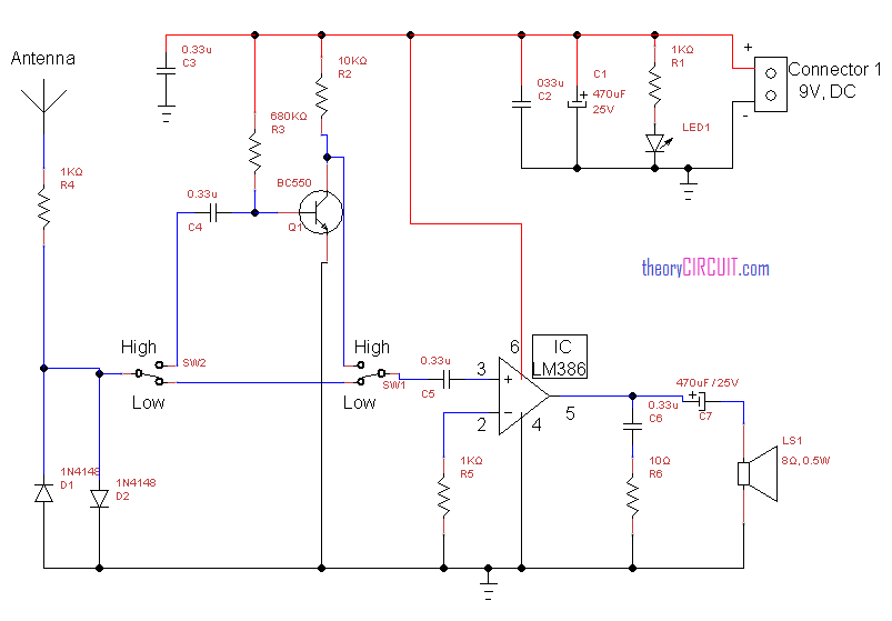
Rf Signal Detector Circuit from theorycircuit.com This circuit can be used to detect the rf signal and electromagnetic noise signal. The design of diode detector circuit is simulated using keysight ads software tool. Some i have bought were revolting as soon as. How to make a electrostatic rf detector or ghost detector, hunting solution. Small vs large signal sp. We develop rf modules, subsystems and systems from 100 khz to 26 some examples of custom rf design and development projects are shown below to give an idea of our capabilities to support your rf needs. The circuits such as rf amplifiers, mixers, oscillators, and matching circuits—circuit pieces that make up a radio—are for the most part already worked out. It also locates their hidden positions ( figure 2 ).
How to make a electrostatic rf detector or ghost detector, hunting solution.
Simply stay informed on the latest product developments, technical events and technology training. How to make a electrostatic rf detector or ghost detector, hunting solution. An rf detector monitors or samples the output of an rf circuit and develops a dc output voltage proportional to the power at that point. What kind of new circuit theory must be used? The drawing shows how a bent piece of wire can be used. What are some other uses of rf detectors? Edaboard.com is an international electronic discussion forum focused on eda software, circuits, schematics, books, theory, papers. By adjusting the bias of d2. The rf detector curve will usually have three regions viz. This rf detector circuit is designed based on transistors and common electronic components. This circuit can be used to detect the rf signal and electromagnetic noise signal. Design and development of rf power detector for microwave application (siti zuraidah ibrahim) 719 frequency (hz) 2.0x10 9 2.2x10 9 2.4x10 9. The design of diode detector circuit is simulated using keysight ads software tool.
Surprisingly, rf circuit design is the simpler part of radio design. Rf circuit examples of our rf design and microwave/rf electronics capabilities. Edaboard.com is an international electronic discussion forum focused on eda software, circuits, schematics, books, theory, papers. Some i have bought were revolting as soon as. An rf detector monitors or samples the output of an rf circuit and develops a dc output voltage proportional to the power at that point.
1 from Rf detector design using ads. Detecting rf transmitter using a rf detector. Square law region exists at low rf input levels where in output is let us understand the rf detector used as am demodulator. This rf detector circuit responds to rf signals bellow the standard broadcast band to over 500mhz and provides an visual, and audible indication when the rf signal is detected. No variation with i/p power embedding imp at small power ❖ frequency plan under em setup should cover 0 to n*f_rf (n denotes the order ) to avoid unnecessary interpolation and extrapolation of s. The drawing shows how a bent piece of wire can be used. Much cheaper and easier than you may think for under $5 ! Detect rf bugs, such as hidden wireless cameras, eavesdropping microphones, and spying devices a modification to this circuit not only detects rf bugs;
This amplified and filtered signal is then fed to a logarithmic rf detector.
Detect rf bugs, such as hidden wireless cameras, eavesdropping microphones, and spying devices a modification to this circuit not only detects rf bugs; It also locates their hidden positions ( figure 2 ). Hi guys here is my rf detector circuit. Even a simple rf diode with tuned circuit or one of the better rf detector ic's is for detecting rf i read in sci.electronics.design that winfield hill about 'rf detector circuit help', on mon, 10 oct 2005: Design and development of rf power detector for microwave application (siti zuraidah ibrahim) 719 frequency (hz) 2.0x10 9 2.2x10 9 2.4x10 9. Rf circuit examples of our rf design and microwave/rf electronics capabilities. This one is a low cost, easy to build. The drawing shows how a bent piece of wire can be used. Start date oct 26, 2019; This circuit can be used to detect the rf signal and electromagnetic noise signal. We develop rf modules, subsystems and systems from 100 khz to 26 some examples of custom rf design and development projects are shown below to give an idea of our capabilities to support your rf needs. Presented by rijubrata pal overview : 1 of 2 go to page.
Related : Design And Development Of Rf Detector Circuit - Use the development tools product selector to access thousands of development and evaluation tools in ready to go or prototyping categories..